Are you looking to design plastic fasteners quickly and accurately in SolidWorks? You’re in the right place.
Creating a plastic fastener model can seem tricky at first, but with the right steps, you’ll save time and avoid common mistakes. This guide will show you exactly how to build your plastic fastener from scratch, even if you’re new to SolidWorks.
By the end, you’ll feel confident to create precise designs that fit your project needs perfectly. Ready to master this essential skill? Let’s dive in!
Credit: www.youtube.com
Setting Up Your Workspace
Setting up your workspace correctly is the first step in creating a plastic fastener in SolidWorks. It helps you work faster and avoid mistakes. A well-prepared workspace makes your design process smooth and efficient. Spend time adjusting your settings before you start modeling.
Focus on two main areas: units and dimensions, and choosing the right template. These settings affect the accuracy and style of your work. Let’s explore how to set these up properly.
Configuring Units And Dimensions
Start by setting the units to match your project needs. Most plastic fasteners use millimeters for precise measurements. Open the “Options” menu and go to “Document Properties.”
Select “Units” and choose millimeters or inches depending on your design. Set the decimal places to 2 or 3 for better accuracy. This ensures your fastener parts fit perfectly.
Check the dimension display style. Use simple and clear formats. Avoid complex units that might confuse you or others working on the file. Correct units keep your design consistent.
Choosing The Right Template
Templates define the starting point of your design. They include preset units, views, and other settings. Pick a template that fits plastic parts or mechanical design.
SolidWorks offers standard templates for parts and assemblies. Choose a part template for a single fastener. For multiple components, select an assembly template.
Custom templates save time in future projects. You can create one after finishing your setup. Using the right template avoids extra adjustments later.
Credit: www.goengineer.com
Sketching The Base Profile
Sketching the base profile is the first step in creating a plastic fastener in SolidWorks. This sketch forms the main shape of the fastener. Keep your sketch simple and clear. Use basic shapes to outline the fastener’s key parts. Make sure the sketch is fully defined to avoid errors later.
Start by focusing on the fastener’s head and shaft. These parts need precise dimensions for a good fit. A clean sketch here saves time during 3D modeling. Let’s break down how to draw these two parts.
Drawing The Head Shape
Begin with the head of the fastener. Use a circle or polygon to create the outline. The shape depends on the type of fastener, like a round or hex head. Set the correct diameter and thickness. Use centerlines for symmetry and alignment. Add any chamfers or fillets for smooth edges. This step ensures the head looks realistic and fits well.
Creating The Shaft Outline
Next, sketch the shaft of the fastener. Draw a straight line or rectangle for the shaft’s length and width. Define the shaft diameter and length carefully. Include threads or ridges if needed by adding small details or patterns. Use construction lines to keep the sketch organized. This outline shapes the part that will hold the fastener in place.
Extruding The Main Body
Extruding the main body is a key step in creating a plastic fastener in SolidWorks. This process turns your 2D sketch into a 3D shape. The main body forms the base of the fastener. It defines the basic size and shape. Precise extrusion helps ensure the fastener fits and functions well.
Focus on the right tools and settings. SolidWorks offers simple controls to extrude with accuracy. Understanding these options saves time and improves design quality.
Applying Extrude Boss/base
Start by selecting the sketch of your fastener’s profile. Click on the “Extrude Boss/Base” feature in the SolidWorks toolbar. This tool adds thickness to the sketch.
Check the preview to see the 3D shape forming. Make sure the base looks solid and matches your design. This step builds the core volume of the fastener.
Adjusting Depth And Direction
Set the extrusion depth by typing a value or dragging the arrow. The depth controls how thick the main body becomes. It is important to match the thickness needed for strength.
Choose the extrusion direction next. You can extrude outward, inward, or both ways. Direction controls the shape orientation and helps fit assembly needs.
Review your choices. Confirm the shape looks correct from all sides. Adjust depth and direction to get the exact form required.
Adding Detailed Features
Adding detailed features to your plastic fastener model in SolidWorks improves its realism and function. Small elements like threads, ribs, slots, or grooves make the part more practical. These details also help during manufacturing and assembly.
Focus on accuracy when creating these features. SolidWorks offers tools to add fine details without overcomplicating the model. Keep the design simple but precise to save time and resources.
Modeling Threads Or Ribs
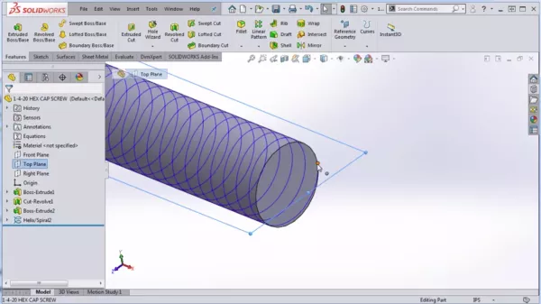
Threads are essential for fastening parts securely. Use the Helix and Spiral tool to create accurate threads. Set the pitch, diameter, and length to match your fastener’s specifications.
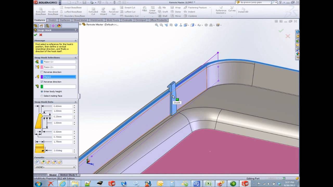
Ribs add strength and reduce material use. Create ribs by sketching thin, raised features on the fastener body. Use the Rib feature to quickly extrude these details. Place ribs where the fastener needs extra support.
Incorporating Slots Or Grooves
Slots and grooves help with alignment and assembly. Sketch a profile for the slot or groove on the fastener surface. Use the Cut-Extrude feature to remove material precisely.
Slots can also reduce stress by allowing slight flexing. Grooves often hold seals or rings in place. Add these features carefully to maintain the fastener’s strength.
Applying Fillets And Chamfers
Applying fillets and chamfers is essential in designing plastic fasteners in SolidWorks. These features help improve the part’s strength and usability. They also prepare the design for manufacturing by reducing stress points and making the edges safer.
Fillets create rounded edges, while chamfers form beveled edges. Both techniques smooth transitions between surfaces. This reduces sharp corners that can cause cracks or breaks in the plastic. Applying these elements carefully ensures better product performance and durability.
Smoothing Edges
Fillets soften the sharp corners of the fastener. They spread the stress over a wider area. This prevents cracks during use or assembly. In SolidWorks, you can select edges and specify the radius for the fillet. Small fillets work well for tight spaces. Larger fillets help in areas that bear more load. Chamfers cut the edges at an angle, removing sharpness. This makes the fastener safer to handle. Use chamfers on edges that fit into other parts. They guide the fastener smoothly into place.
Enhancing Aesthetics And Function
Fillets and chamfers improve the visual appeal of the fastener. Rounded and beveled edges look more polished and professional. This is important for visible parts in assemblies. These features also reduce material wear during installation. Smooth edges cause less friction and damage. They help the fastener slide easily into holes or slots. Properly applied fillets and chamfers can improve the overall function of the design. They make assembly faster and reduce the risk of breakage.

Credit: www.youtube.com
Material Selection And Appearance
Choosing the right material and appearance is important when creating plastic fasteners in SolidWorks. These choices affect how your model looks and behaves. Good material selection ensures the fastener meets strength and flexibility needs. Appearance settings help you visualize the final product clearly.
Choosing Plastic Materials
Select plastics based on strength, flexibility, and temperature resistance. Common choices include ABS, Nylon, and Polypropylene. Each plastic type has unique properties for different uses. Consider the fastener’s environment and load requirements. Use SolidWorks material library to assign accurate material data. This helps in realistic simulation and analysis.
Assigning Colors And Textures
Colors help identify parts easily in your assembly. Choose colors that match your brand or product design. Textures add realism to your fastener model. SolidWorks allows adding smooth, matte, or rough finishes. Adjusting these settings improves the visual appeal. It also helps clients and teams understand the design better.
Validating The Design
Validating the design is a key step in creating a plastic fastener in SolidWorks. It helps ensure the part fits and works correctly. Validation saves time and cost by finding errors early. This process improves the quality of your final product.
Checking Dimensions
Start by measuring all important dimensions of the fastener. Use SolidWorks tools to check length, width, and thickness. Confirm the size matches your design requirements. Small mistakes in dimensions can cause big problems later. Make sure holes and slots are in the right place. Accurate dimensions help the fastener fit perfectly in its assembly.
Running Simulations
Run simulations to test the fastener’s strength and performance. Use stress and strain analysis within SolidWorks. Simulations show how the part reacts under pressure or load. Check for weak points that could cause failure. Adjust the design if the fastener does not meet strength needs. Simulations reduce the risk of product failure after production.
Preparing For Production
Preparing for production is a key step in creating plastic fasteners in SolidWorks. This phase ensures your design is ready for manufacturing. It helps avoid mistakes and saves time. Proper preparation leads to smooth production and high-quality parts.
Two important tasks in this stage are generating technical drawings and exporting CAD files. Both tasks provide clear information for manufacturers. Let’s explore how to do these steps effectively.
Generating Technical Drawings
Technical drawings show detailed views of the plastic fastener. These drawings include dimensions, tolerances, and material notes. Use SolidWorks to create clear and accurate drawings. Make sure all critical features are visible. Include all necessary measurements for manufacturing. Clear drawings reduce errors during production.
Exporting Cad Files
Exporting CAD files allows you to share your design with manufacturers. Use standard formats like STEP or IGES for compatibility. Check file settings to keep all details intact. Export files at the correct scale. This step ensures manufacturers receive accurate information. Good file export helps avoid delays and confusion.
Frequently Asked Questions
What Are The Basic Steps To Create Plastic Fasteners In Solidworks?
Start by sketching the fastener profile, then use the Revolve or Extrude feature. Add threads using the Helix tool. Finally, apply material properties to simulate plastic behavior accurately.
How Do I Model Threads On Plastic Fasteners In Solidworks?
Use the Helix and Sweep features to create realistic threads. Adjust pitch and diameter to match specifications. This method avoids heavy computations and keeps the model lightweight.
Can I Simulate Plastic Material Properties In Solidworks?
Yes, apply plastic material properties from the SolidWorks material library. This simulates flexibility, strength, and deformation under stress. It helps optimize your fastener design for real-world use.
What Tools Help Optimize Plastic Fastener Design In Solidworks?
Use SimulationXpress for stress analysis and Draft Analysis for moldability checks. These tools ensure your fastener meets strength and manufacturing requirements efficiently.
Conclusion
Creating a plastic fastener in SolidWorks takes some steps. Start by choosing the right shape and size. Use simple tools like extrude and revolve to build parts. Check your design carefully to avoid errors. Practice helps you get faster and better.
Keep learning new tips to improve your skills. SolidWorks lets you design strong, precise fasteners easily. Try it yourself and see how designs come to life.